[ This is the original page describing my attempts to turn a robot arm into a bartender. It worked (!) and you can see a more complete description as well as pictures and video here. ]
 Well, on October 1, 2002, I became the proud owner of a Kawasaki/Puma/Unimate
200 Model robotic arm, saved from certain doom (in the dumpster) from
Northeastern University. Since then, I've been on the long and often
meandering path towards getting the arm working again.
You can see pictures of the arm and controller in various states of
deconstruction (when I got it) here.
Well, on October 1, 2002, I became the proud owner of a Kawasaki/Puma/Unimate
200 Model robotic arm, saved from certain doom (in the dumpster) from
Northeastern University. Since then, I've been on the long and often
meandering path towards getting the arm working again.
You can see pictures of the arm and controller in various states of
deconstruction (when I got it) here.
And you can read about my latest attempts to reanimate it below...
October 15, 2012 - It's true, I haven't spent as much time as I might have liked on the robot arm this year, but I also don't think the 8 month lag in posting accurately reflects the measurable progress I've made.
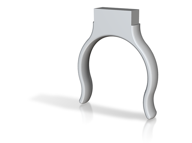
For starters, I took the shape of the wooden part I'd made for the gripper and turned into a 3D model, then called in a favor to a friend who printed it for me.
Next, I made a prototype of the table for the bartender.
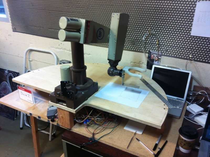
And finally, most recently, and perhaps most importantly, I took some time to really measure the joint-to-joint distances and dial in the gear ratios (this is what enables the transformation between motor encoder counts and joint angles, and ultimately between motor encoder counts and XYZ space). In the photo above, you can see a piece of paper on the table, and a parallelogram drawn on that piece of paper. Sadly, that's supposed to be a square. Something in the software was off.
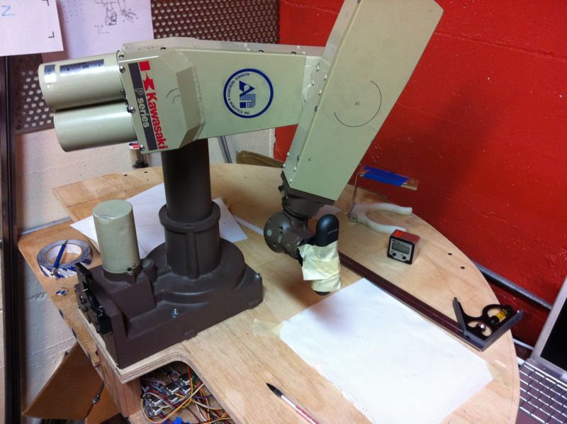
You can see I temporarily taped a laser pointer to the wrist so I can accurately mark points a piece of paper taped to the table, and in the background of that photo, you can see the handy tool I used to calibrate the angles. I zeroed the gauge, commanded the arm to move 45°, read the measured angle, and changed the gear ratio by the difference. Worked like a charm!
Next up is some long-overdue PID tuning.
February 8, 2012 - A quick update since I managed to get the arm pouring a drink!
December 19, 2011 - Three years later, it's most definitely time for an update! If you've been keeping up on my blog, you know that I haven't been ignoring dear old PUMA 260 since 2008. Quite to the contrary, much progress has been made.
To rewind back to the last update, I'd gotten one of the joints working with my custom PCBA. After some more investigation, it became clear that the circuit I'd designed worked well enough to eke out a little motion in the wrist, but not well enough to drive them with sufficient strength, and definitely didn't have enough power to drive the larger motors in the first three joints of the arm.
Sad as I was to give up on using my own circuit board, it just made sense. I'm not an electrical engineer, and while I'm sure I could have made it work eventually, it could've taken years, and probably wouldn't have been much fun. Plus, it turns out people already have designed (and sell for reasonable prices) perfectly good motor controllers. I chose this one.
It didn't take that much effort to get the new motor controller hooked up (didn't hurt that once again Matt was visiting) and driving motors in the arm. Once I'd proved I could control any of the joints, I went ahead and ordered 5 more controllers (one for each joint), along with a few of these solid-state relay (SSR) boards to engage and release the electromagnetic brakes on the first three joints. I still had the old USB-to-I2C board, and it happens to have a set of general purpose I/O pins on it, along with the serial communications. I'm using a few of these to communicate with the SSR boards.
This is what the system looks like these days:
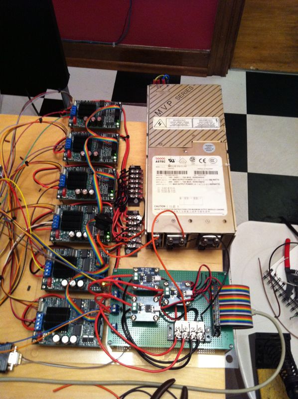
And not too long after I got all those boards hooked up, I got to the point where I could control all the motors.
Not too shabby, and once again, I got to utter the (in)famous phrase, "Now it's just software!" It will likely come as no surprise that software can be quite tricky...
But software can also be quite interesting, especially when it connects to a device with moving parts, and so I lept into the world of kinematics. As I mentioned before, having a PhD roboticist brother is handy, especially when you're piecing together a robot bartender, and Matt provided me with some handy code to convert back and forth between joint angles and XYZ space. After quite a bit of futzing and tuning, I got his code integrated with mine and wrote a little interpreter so I could script the motion of the arm.
Along the way, I discovered some funny business with the wrist joint in this arm — it turns out the three motors don't actually drive the wrist axes independently. Instead, they're coupled, like a differential, and to move only one axis on the wrist requires driving multiple motors. After including some math to account for this, I was in business!
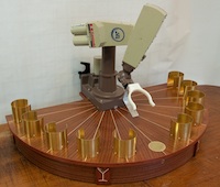
Which brings us to today:
There's still plenty to do (including some woodworking/construction to make an appropriate rack to hold bottles), but it's come a long way!
December 4, 2008 - It's been quite a week in the world of robot arms that happen to be in my living room:
Yep, that's the full system working, end-to-end. My mac (not visible in the video) sends commands via USB to the USB-to-I2C translator, which sends them to the microprocessors on the circuit board (with the blinking lights), which send signals to the motor controller chips (screwed to the big hunk of aluminum that spans the board), which sends power through the tangle of wires through the arm to the motors, which, in turn, send position information back through the wires to the circuit board. Phew!
It's not all working 100% just yet, though. Either there's some loss in transmission of the power to the motors, or I'm not sending enough to start with, because 4 out of 6 motors aren't working in place. But, it is a big step.
The other big step was getting a great software handoff from my brother, Matt. Turns out, if you want to make a robot arm work, it really helps to have a brother getting a PhD in robotics. He wrote a sweet little program that not only translates from an (X, Y, Z) position and orientation of the end effector into joint angles, but it actually displays them all on screen:
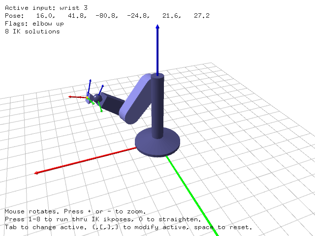
So there's some debugging left to do, and some software to write, but I'm really excited about all the progress!
November 17, 2008 - Just because it's been a while since I updated this page doesn't mean I haven't made any progress in the past 9 months.
I did manage to finish assembling the board, and got the PSoC's up and running (no trouble programming them on the board, as long as I disconnect the I2C header). In fact, almost all the functionality checks out using the smaller motors from the arm - I can use the LM18200 to control the motor, the encoder counts are read in properly, I have a rudimentary PID controller in place (to be refined once the motors are back in the arm), and I can communicate to the processors via I2C. Awesome!
What's left, then? Well, a couple things remain on the electronics side before it becomes merely a software project: the power supply and the electromechanical brakes on the larger motors.
I got a recommendation for a modular power supply from a friend, but in the end just couldn't stomach the $500 price tag. EBay to the rescue! I found this and bought it, but it turned out to be a dud (a friend and I spent a couple hours trying to get it working, to no avail). A few more clicks later, and this bad boy was on its way to my house. It's slated to show up Thursday, and hopefully progress can resume.
The other issue is about the larger motors. Because they control heavier parts of the arm, they're fitted with electromechanical brakes (basically just solenoids with brake pads on the shaft of the motor). I put down some load switches on the board to disengage the brake (just run some current through the coil), but I'm worried I'll need the higher power version.
I should be back on track to do some programming within a week or so!
February 17, 2008 - Just before I left for San Francisco, I got the boards back from 4pcb:
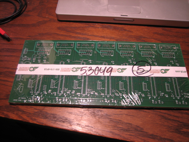
They did a great job with them - I haven't found any problems.
And I've started assembly:
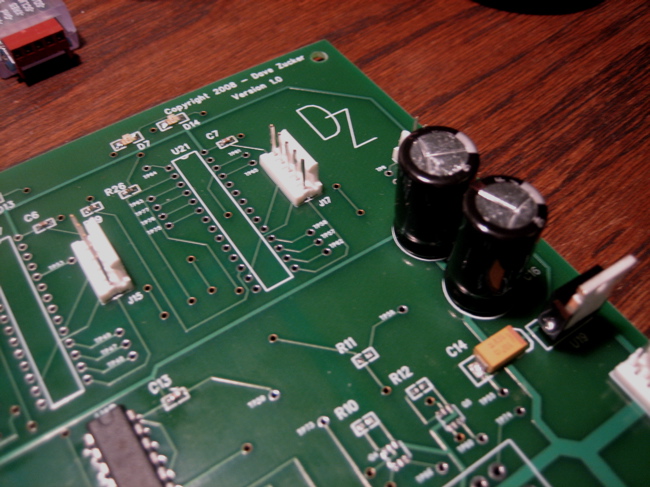
I haven't put down the PSoC processors yet 'cause I've had problems in the past where the in-circuit programming hasn't worked - I've got another DigiKey order in for some IC sockets so I can take the chips out and program them on a prototype board if need be.
I've had a little trouble soldering pins that connect to ground since there's a large ground plane on the back of the board that soaks up the heat. On the advice of my EE friends, I included thermal vias on those pins, but it's still tough to get them hot enough for the solder to flow. Any advice?
By the way, soldering 0603 packages by hand with no microsope is tough! If I redid the layout, I'd bump those resistors and capacitors up to 0805's or 1206's for sure.
January 24, 2008 - I sent the PCB files off to 4pcb for fabrication yesterday! They should be done in a week or so, and in my hands in early February. The only downside to ordering through them is they don't do internal routing on the PCB, so the four holes in the corners won't be included. I can always drill them by hand, though, and it was worth it considering 4pcb was 50% of the cost of the next cheapest board house.
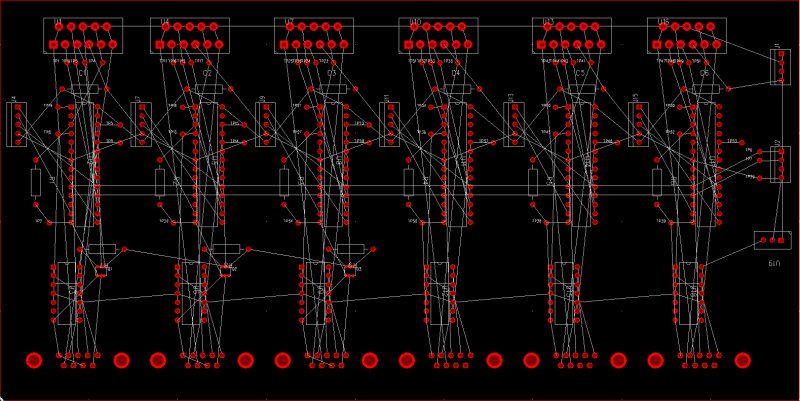
January 8, 2008 - The PCB layout is done (click for larger version):
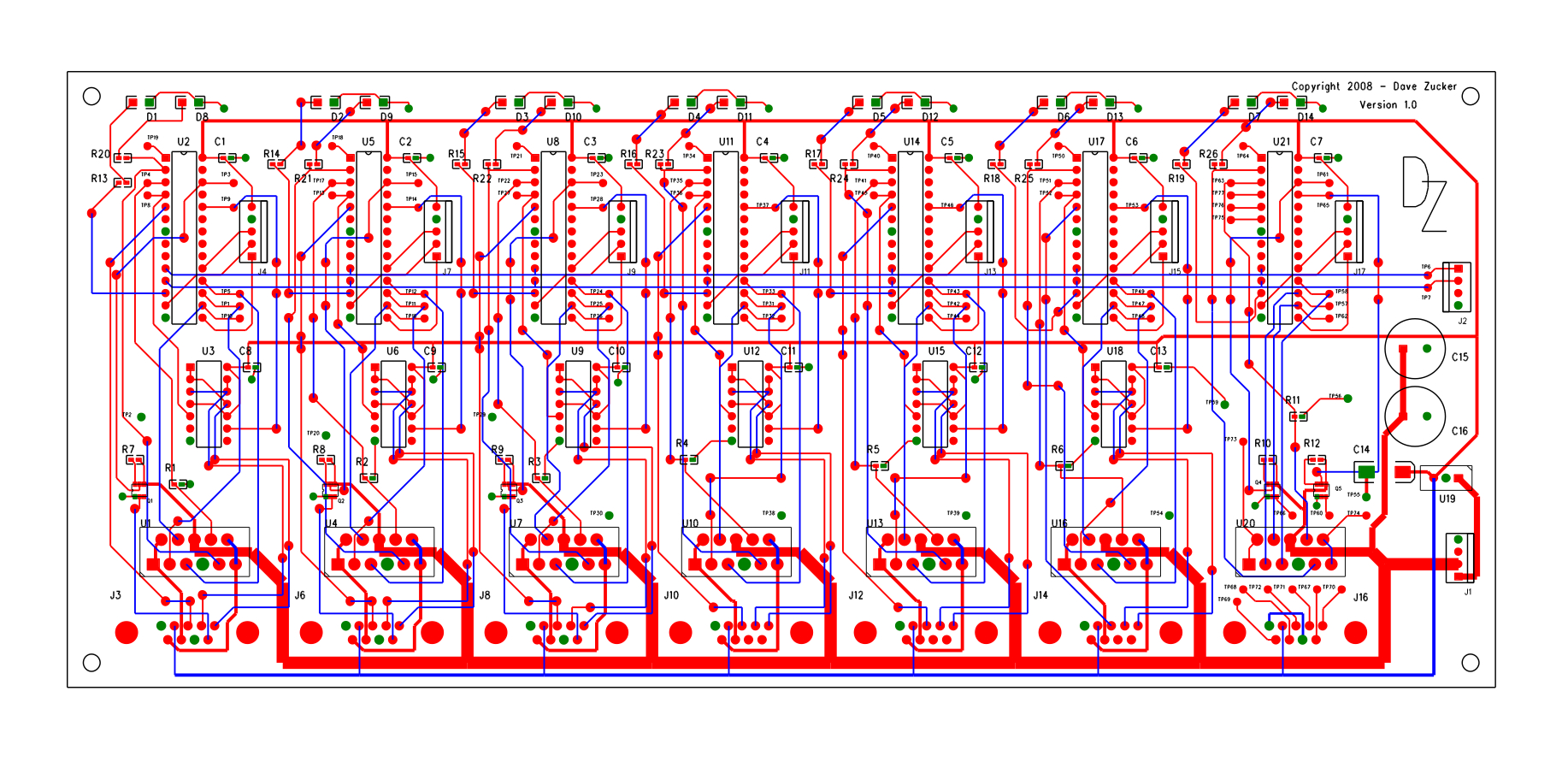
Red traces are on the top of the board, blue on the bottom. Green pads mean it's connected to ground, and everything in black (part outlines, names, etc.) is silkscreened on to the board. Not shown is the large copper pour (which acts as a ground plane) on the bottom of the board. The board is approximately 11.5" x 4.75".
I'm shopping PCB fab houses this week and will have the board made sometime soon. Progress!
December 29, 2007 - The PCB layout is getting awful close to done:
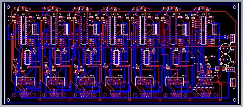
This last iteration bumped up the board size a hair (since there aren't any physical constraints on the size) and added a bunch of LED indicators. Can't have homemade electronics without blinkenlights!
Just 'cause it'd be fun, I'm tempted to make a nice plot of the layout with the new plotter (and I guess it might actually help finding layout issues).
December 3, 2007 - After some more professional advice (thanks, Brian), I'm getting better at PADS, and I'm nearly done with the layout of the PCB:
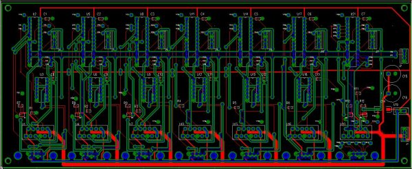
I probably won't actually have the board made until I get a job, but it's more or less ready to go.
I've also been playing some with my breadboard prototype, and started writing some control code. I'll probably call on Matt's expertise soon to finish that effort.
November 1, 2007 - Thanks again are due to Jordan, this time for helping debug the I2C problem I was seeing. Turns out it was nothing directly wrong with the I2C bus, but instead an improperly set variable that made another process run way faster than intended. Instead of running my timer interrupt code once a second, it was happening about 1000 times a second, and ended up causing delays with I2C, but only some of the time.
The nearly infinite configurability of the PSoC seems to be both a blessing and a curse. This definitely isn't the first time some seemingly insignificant setting in the PSoC Designer IDE has caused a difficult-to-debug problem.
In any event, I'm glad it's been identified, and I'm looking forward to finishing up the layout and starting work on the control software.
October 15, 2007 - Layout hit a bit of a speedbump when I got laid off from my job and didn't have access to PADS anymore. Jake and Jordan fixed me up, and I'm back at it.
I've routed all the traces, but I'm sure that I made some mistakes. I'll get a couple real EE's to look over the design before I send it off.
Also slightly disconcerting are the intermittent errors I see on the I2C bus. Can't tell if it's grounding issues, noise on the wires, or something more insidious.
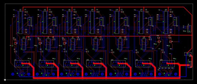
April 30, 2007 - I'm about 99% done with the schematic for the circuit board, and I've started the layout:
After a little more layout and a review by some coworkers, I'll have someone print up some boards. Getting there!
October 6, 2006 - Been playing with the PSoC recently, and made a bunch of progress. Last week, I got I2C working so I can communicate between my Mac and the processor.
And then today, with the help of this article, I hooked up the encoder outputs to two D flip-flops. The flip-flops split the encoder pulses into two pulse-trains, an clockwise signal and a counterclockwise one. I fed those signals into two counters on the PSoC, so now I can get the motor position just by subtracting one from the other:
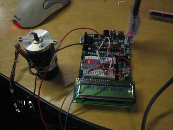
The number on the left is the "up" counter value, the middle is the "down" counter, and the right is the difference, or the position.
From here, I've gotta get the motor driver chip working with the PSoC, then spin a circuit board with 6 sets of processors, decoders, and motor drivers. From there on out, it's just software... famous last words.
August 31, 2006 - After much experimentation this spring, I discovered that the PIC just isn't fast enough to keep up with the motor encoders.
Coworkers have recommended checking out the PSoC, which I've started to do. Definitely no Mac development environment, though.
December 25, 2005 - At last! I found a discussion of (and fix for) a compiler bug that causes the invalid HEX file problem. I can now compile a C program on my Mac and load it onto the PIC. Woo!
December 21, 2005 - Progress! Using updated firmware on the programmer and Jeff Post's pk2, I can now transfer HEX code onto the microcontroller (note - you need to use the -programall option, otherwise the configuration word on the PIC isn't written properly).
I thought I was home free, but unfortunately not so - the C compiler I'm using, PICC Lite seems not to produce valid HEX files when it compiles C code. I'm still investigating the problem, but have figured out a way to get things going for now. More details as I figure it out.
December 11, 2005 - I've been doing some work on getting a small circuit together to control each motor (there are six in the arm). My plan is to use a microcontroller PIC (from Microchip) in conjunction with a motor control chip (H-bridge) like the Allegro 3959.
To get started, I bought a USB PIC programmer and demo board, thinking it'd work easily with my Mac. Turns out, almost everyone who does PIC programming does it from Windows, and the those who don't use Windows use Linux. Through the magic of the Internet, I've found some folks who're trying to get stuff running on the Mac. Very helpful has been Ben Brooking's evolving PIC development for Mac OS/X page. I've exchanged some emails with him and we're close to getting the PICKit 2 programmer working under Mac OS/X.
December 30, 2003 - I found a student project that uses the Puma 500 robot arm. Also found a paper on the PUMA 560. And finally, some guys who bought an arm at an auction and got it working.
April 22, 2003 - I added a servo page with new infomation from AR2.
April 21, 2003 - I added some more pictures in the controller section [removed] and some new links here:
- A Carnegie Mellon website on robot arms.
- The Trident/Mark V Robotics website.
- The Advanced Research Robotics homepage.
I've found some information on the web about the arm. Check it out here:
- Puma Servo Documentation - document describing the Unimation Servo System.
- Trident Servo Controller - board intended to replace the huge original electronics package.
- RP Automation - A Puma Reseller.
- Some reference information on a motor driver chip here.
- Some decoders: a chip, the LS7166 and a board, the PC7166.
- I found an Australian company called Tritium that sells new (small!) controller boards for the Puma arm.
- Antenen has what seems to be the original datasheet for the PUMA 260.